I’ve wanted to do a home power monitoring project for some time. I was using a Clipsal Cent-a-meter a while ago to track power usage when I lived in Victoria but I didn’t have much luck with the newer model. It didn’t have a good range and seemed to lose connection between the base and sending unit. So I thought I would go DIY.
I looked at lots of different systems including PIC microcontrollers but I decided to give the JeeNode and JeeLink combination a try. It seemed like a good choice for the following reasons:
- Arduino compatible
- Low power (3.3V)
- Integrated wireless
- Easy interfacing with a PC (JeeLink)
- Expandable
In our house we have a smart meter which has a blinking red light for every Watt Hour of power used. So by measuring the length of the pulse you can have an indication of instantaneous power usage. This saves using clip on CTs which need to be installed by an electrician. The other advantage of using the smart meter is that this is the actual power usage I am being charged for. The only problem with this is that in Tasmania we have two different tariffs, one for normal usage and one for heating (cheaper). My system doesn’t take into account the tariffs and can only measure total usage. It also could not be used with electricity generation because the smart meter only blinks for imported power, if you are generating then the actual power usage will be higher than the imported.
So I went to Modern Device and ordered the following:
The JeeNode will be used to monitor the blinking light, which will send data to the JeeLink (plugged into my HTPC running Ubuntu) and the USB BUB II is required for programming the JeeNode.
I soldered the JeeNode and JeeLink up when they arrived on the coffee table while watching something mindless on TV. It had been a while since I had done proper soldering and with a good temperature controlled iron it was pretty easy. I should get some good quality solder though!
I tested the JeeNode and JeeLink and they worked first time. Now to look for some code.
I ended up using this code http://jeelabs.net/projects/cafe/wiki/Electricity_consumption_meter I modified it to suit the 1Wh blinks and using a LDR.
Here is my version of the transmitter code:
// Reading Comparator input

#include <Ports.h>
#include <RF12.h>
#include "kWh.h"

class Port;
Port inputPort(1);
static unsigned long last;

void setup() {
    inputPort.mode2(INPUT); // Set AIO mode as input
    inputPort.digiWrite2(1); // Activate pull-up resistor for AIO

    rf12_config();
    rf12_config(); // Apparently this is necessary
    rf12_easyInit(3); // Send value at most every 3 seconds
    last = millis();
}

void loop () {
    static boolean ledOn = false; // Variable to indicate LED status
    int data = inputPort.anaRead();
    rf12_easyPoll();
    if (!ledOn && data > 750) {        // After testing I found the switching point was 750
        ledOn = true;
    } else if (ledOn && data < 750) {
        ledOn = false;
        ledBlink();
    }
}

void ledBlink() {
    static int nBlinks = 0;
    unsigned long time = millis();
    unsigned long interval = time - last;

    nBlinks++;
    if (interval < 0) { // millis() overflow
        last = time;
        nBlinks = 0;
    } else if (interval > 1000) { // 1+ sec passed
        // Blinks are 1000 per kWh, or 1 Wh each
        // One hour has 3.6M milliseconds
        long watts = nBlinks * 1 * 3.6E6 / interval;

        wattSend(watts);
        last = time;
        nBlinks = 0;
    }
}

static void wattSend(long watts) {
    Packet_t packet;
    packet.lang = LANG_ELECTRICITY;
    packet.mesg = MESG_ELEC_CURRENT;
    packet.data = watts;
    rf12_easySend(&packet, sizeof packet);
}
And here is my version of the JeeLink receiver code
#include <Ports.h>
#include <RF12.h>
#include "kWh.h"

void setup() {
    Serial.begin(57600);
    rf12_config();
    rf12_config();
}

void loop() {
    if (rf12_recvDone() && rf12_crc == 0 && rf12_len == sizeof (Packet_t)) {
        Packet_t packet = *(Packet_t *) rf12_data;

        if (packet.lang == LANG_ELECTRICITY) {
            if (packet.mesg == MESG_ELEC_CURRENT) {
                wattShow(packet.data);
            }
        }
    }
    else {
        delay(10);
    }
}

static void wattShow(long watts) {
    Serial.print("Usage: ");
    Serial.print(watts);
    Serial.println(" W");
}
I connected 4 AA NiMh batteries as the power supply to the JeeNode and sat it on top of the smart meter. The LDR is connected between the AI pin and ground of one of the ports.

Pretty isn’t it?
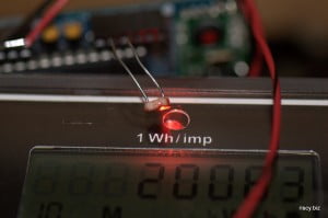
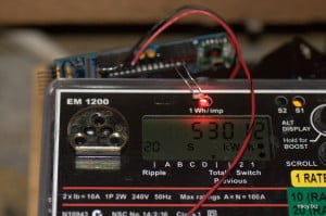
The LDR is right next to the LED
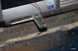
The JeeLink is connected to my PC running Mythbuntu, which is my HTPC.
Ubuntu is running Perl code to read the serial port and dump it to a file which timestamps the incoming data.
use strict;
use warnings;
use Device::SerialPort;
use POSIX qw/strftime/;

my $port = Device::SerialPort->new('/dev/ttyUSB0');
my $time = time;

if( ! defined($port) ) {
        die("Can't open /dev/ttyUSB0 $^E\n");
}

my $outfd;
open ($outfd, ">>", "log.txt") or die "Failed to open output file - $!n";

my $output = select(STDOUT);
$|++;
select($outfd);
$|++;
select $output;

$port->baudrate(57600);
$port->parity('none');
$port->databits(8);
$port->stopbits(1);
$port->write_settings();
$port->are_match("\n");

while(1) {
    my $char = $port->lookfor();
    if ($char) {
        $char =~ s/\xd//g;
        my ($watts)= $char =~ /(\d+) W/;
        print strftime('%d-%m-%Y %H:%M:%S',localtime);
        print ",$watts\n";
        print $outfd strftime('%d-%b-%Y %H:%M:%S',localtime);
        print $outfd ",$watts\n";
    }
}
$port->close();
exit(0);
It works and the next step is to make a nice graphing utility. I’ll post again when I have some pretty graphs. At the moment I’m just dumping all the data into Excel.
Try this:
http://stackoverflow.com/questions/2012852/control-a-perl-scripts-cpu-utilization
http://jeelabs.net/projects/cafe/wiki/POF_03_-_Wireless_light_sensor
Look at the low power section of this too